
Compreender as falhas comuns f Transdutores ultrassônicos
Reconhecer sintomas de falha do transdutor ultrasônico
Detetar esses sinais de alerta precoce pode impedir falhas graves do sistema antes que elas aconteçam. Cuidado com sinais que entram e saem, níveis de som mais fracos do que o normal e acúmulo de calor inesperado ao redor do local onde o transdutor se conecta a outros componentes. Não ignore também os danos físicos - cabos desgastados ou coberturas rachadas de lentes precisam de reparação imediata. De acordo com uma recente pesquisa da indústria do Industrial Sensors Quarterly no ano passado, cerca de sete em cada dez problemas menores com transdutores são mal interpretados pelos sistemas de processamento à primeira vista. Estes erros geralmente geram problemas maiores quando os técnicos não os apanham cedo o suficiente.
Como os componentes dos transdutores afetam a fiabilidade do sistema
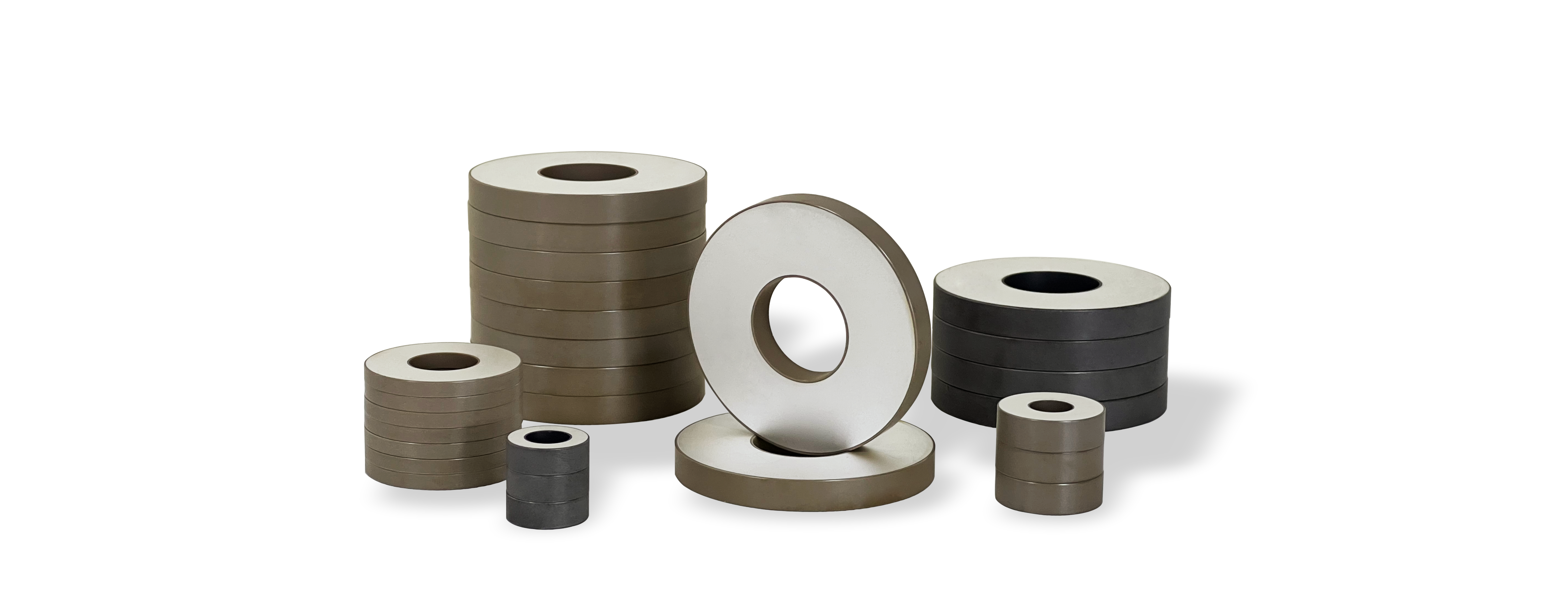
As matrizes de cristais piezoelétricos tendem a degradar-se com o tempo devido a todo esse ciclo térmico e ao constante stress de vibração, o que leva a uma deriva de frequência notável eventualmente. Quando as camadas correspondentes começam a descascar, elas espalham os feixes de ultra-som em vez de os focalizarem adequadamente. E não me obrigue a falar do que acontece quando o epoxi no material de apoio começa a liquefazer - só cria estes vazios internos irritantes que ninguém quer. O verdadeiro problema, porém, vem com os selos impermeáveis. Muitas vezes falham porque diferentes partes da casa encolhem em diferentes taxas quando as temperaturas mudam. Esta incompatibilidade é responsável por cerca de um terço de todas as falhas iniciais que vemos no campo, tornando a compatibilidade do selo com as temperaturas de funcionamento uma grande preocupação para os engenheiros que trabalham nestes sistemas.
Estudo de caso: Análise de falhas nos sistemas de limpeza industrial
Em uma grande fábrica que fabrica milhares de peças diárias, bolhas de cavitação começaram a desgastar a proteção de titânio ao redor dos transdutores depois de apenas meio ano. Quando fizeram o diagnóstico, descobriram que as frequências de ressonância tinham mudado cerca de 12 kHz porque pequenas rachaduras estavam a formar-se nas estruturas cristalinas. A equipe de engenheiros usou então técnicas de mapeamento de impedância acústica para identificar exatamente onde estavam localizados esses pontos de estresse, já que a força dessas bolhas em colapso atingiu mais de 40MPa em algumas áreas. Decidiram substituir o velho blindagem por um material cerâmico de forma especial que seguisse o caminho natural das bolhas de cavitação. Esta mudança fez uma diferença real - em vez de ter que consertar ou substituir componentes a cada 900 horas, agora eles passam quase 2.200 horas sem encontrar problemas semelhantes.
Estratégia: Monitorização proativa para a detecção precoce de problemas comuns com transdutores de ultra-som
As verificações trimestrais utilizando espectroscopia de impedância combinadas com reflectometria de domínio temporal podem detectar sinais de fadiga cristalina muito antes de aparecerem quaisquer problemas de desempenho perceptíveis. Ao realizarem a manutenção de rotina, os técnicos devem estabelecer leituras de capacidade de base para cada par de transdutores, mantendo uma margem de erro de cerca de 5 pF como orientação geral. A execução de exames de imagem térmica logo após a inicialização é outra boa prática, pois muitas vezes destaca áreas problemáticas onde podem ocorrer vazamentos elétricos ocultos. Este tipo de medidas proativas têm demonstrado reduzir as falhas inesperadas do equipamento de forma bastante dramática. Algumas pesquisas do Instituto de Tecnologia de Manutenção em 2024 sugeriram que as instalações que implementam esses protocolos viram uma redução de aproximadamente 50-60% no tempo de inatividade não planejado ao longo de vários meses.
Diagnóstico e resolução de problemas de saída de sinal
Quando os transdutores de ultrassom produzem sinal fraco ou nenhum, há geralmente três principais culpados por trás deste problema. Primeiro na lista é quando os circuitos dos condutores não combinam corretamente. Depois temos as incompatibilidades de impedância que causam problemas, e finalmente, superfícies acústicas sujas ou contaminadas que não transmitem sinais corretamente. De acordo com descobertas recentes publicadas no International Journal of Advanced Sonication Technology em 2023, cerca de dois terços destes problemas de sinal na verdade se devem a drivers e transductores inadequados. Os investigadores notaram que isto acontece com especial frequência em sistemas mais antigos que são atualizados mas ninguém se preocupa em verificar se as especificações elétricas ainda funcionam correctamente.
Causas da saída fraca ou inexistente de sinal nos transdutores ultrasônicos
Circuitos de driver desajustados geralmente criam discrepâncias de tensão, levando à geração errática de sinal. Os contaminantes como a gordura ou os depósitos minerais nas faces dos transdutores podem amortecer as vibrações em até 40%, enquanto os elementos piezoelétricos rachados, frequentemente devido a tensões mecânicas, causam uma degradação permanente do sinal.
Avaliação da compatibilidade e integridade do circuito do condutor do transdutor
Utilize um processo de validação em quatro etapas:
- Medir a tensão de saída do condutor em relação às especificações do transdutor
- Verificar o alinhamento da impedância com medição de LCR
- Inspecionar o isolamento do cabo para detectar micro-fracturas
- Loops de reação de ensaio com osciloscópios
Estudo de caso: Restauração da saída de sinal em sondas de imagem médica
O sistema de ultra-som de matriz em fase de um hospital mostrou uma sensibilidade reduzida de 70% no sinal durante as varreduras cardíacas. Os técnicos descobriram conectores oxidados e uma queda de tensão de 20% nos condensadores de condutores envelhecidos. Substituindo os conectores e atualizando para drivers de detecção automática restaurou a resolução da imagem às especificações do fabricante.
Estratégia: Diagnóstico passo a passo de falhas frequentes no sinal do transdutor ultrasônico
Implementar testes de isolamento progressivos:
- Realizar ensaios de banco com geradores de sinal calibrados
- Transdutores de troca entre sistemas idênticos
- Analisar padrões térmicos durante o funcionamento
- Realizar varreduras de frequência para identificar mudanças de ressonância
Este método reduz o tempo médio de solução de problemas em 35% em comparação com as abordagens reativas, como demonstrado em um relatório de eficiência de manutenção de 2024 da Acoustical Society of America.
Gestão dos desafios ambientais: temperatura e umidade
Como as variações térmicas afetam o desempenho do transdutor de ultra-som
Quando as temperaturas mudam rapidamente, eles realmente interferem com a precisão dos transdutores de ultra-som porque os materiais expandem e contraem, o que muda a forma como os elementos piezoelétricos ressoam. O tempo quente faz com que as peças se desgastem mais rapidamente, e as temperaturas frias podem tornar as coisas frágeis e propensas a rachaduras. A pesquisa indica que, quando as operações vão além do intervalo seguro de mais ou menos 15 graus Celsius, o desempenho começa a cair em até 12%. Todo este aquecimento e resfriamento constantes colocam um grande esforço nas pequenas ligações de solda e selantes ao redor da caixa. Isso explica porque é que estes sensores tendem a falhar mais frequentemente em locais como as siderúrgicas onde fica muito quente, ou em instalações de armazenamento frigorífico onde as temperaturas flutuam constantemente ao longo do dia.
Prevenção do sobreaquecimento e da condensação em ambientes exteriores e úmidos
Implementar sistemas de arrefecimento integrados e interrupções térmicas entre transdutores e superfícies quentes para dissipação de calor. Para controlo da umidade:
- Transdutores de posição acima do ponto de orvalho utilizando aquecimento local (dispositivos Peltier)
- Manter os níveis de HR de 40 a 60% utilizando respiradores dessecantes
- Instalar tampas de ventilação de absorção de umidade em aplicações tropicais
Os dados de campo mostram que os sistemas que utilizam o monitoramento ativo da umidade experimentam 67% menos falhas nas fábricas de montagem do Sudeste Asiático em comparação com as abordagens passivas.
Estratégias de vedação e de abrigos para evitar danos causados pela umidade
Utilize proteção anti-corrosiva de várias camadas para ambientes marinhos e químicos:
| Método de proteção | Implementação | Eficácia |
|---|---|---|
| Epoxi em vasos | Preenche cavidades com compostos resistentes à umidade | prevenção da entrada de umidade a 95% |
| Soldagem a laser | Outros, de aço inoxidável | Resistência a salinagem > 5.000 horas |
| Casas IP68 | De borracha, de borracha ou de borracha sintética | Protecção contra submersão até 3 m de profundidade |
Estas técnicas praticamente eliminaram falhas de pressão hidrostática em aplicações de ROV do Mar do Norte quando combinadas com renovação trimestral de revestimento hidrofóbico.
Estudo de caso: Garantir a fiabilidade do transdutor ultrasónico em aplicações marítimas
Uma fazenda de energia de onda experimentou 53% de taxas anuais de falha do transdutor por intrusão de água salgada. A implementação de sensores de titânio com duas vedações de anel O e cavidades pressurizadas cheias de nitrogênio reduziu as falhas para apenas 8% em dois anos. A análise pós-implementação verificou que a solução manteve < 0,1% de teor de umidade internamente, apesar da exposição constante a salinhas e de ciclos de imersão de 15 metros.
Minimizar as interferências do sinal e o ruído externo
A operação eficaz do transdutor ultrasônico requer a mitigação da degradação do sinal por perturbadores externos.
Identificação de fontes de interrupção do sinal ultrasônico e de transmissão
Os sinais de interferência geralmente vêm de emissões eletromagnéticas em torno das frequências onde os transdutores funcionam. Os motores que estão perto, todos os aparelhos sem fio a flutuar, até outros transdutores podem causar problemas de transmissão que perturbam a detecção dos ecos. Por exemplo, quando vários sensores ultra-sônicos estão a funcionar ao mesmo tempo em áreas apertadas, acabam por criar sons sobrepostos confusos. Há também o problema dos picos de energia repentinos nas fábricas e aquelas ondas de rádio irritantes a saltar entre 40 e 400 kHz. Para localizar o que está a causar todo este ruído, os engenheiros normalmente fazem análises detalhadas do espectro com equipamentos como analisadores de sinal que os ajudam a identificar exatamente o que está errado.
Causas ambientais e estruturais da degradação do sinal
A perda de sinal aumenta em ambientes com superfícies refletoras ou máquinas ricas em vibrações. As estruturas metálicas causam reflexos de vários caminhos, produzindo falsos ecos. As flutuações de temperatura alteram a densidade do ar, afetando as velocidades de propagação do som em 0,17%/°C de acordo com os princípios da física acústica. O ar com grande quantidade de partículas e a elevada umidade (> 80%) atenuam os sinais, reduzindo o intervalo máximo em 25~40% nas observações de campo.
Estudo de caso: Redução das interferências nos sistemas de estacionamento automatizados
Uma instalação automatizada experimentou 35% de detecção de ocupação falsa devido a interferências de sistemas HVAC e ignições de veículos próximos. Os técnicos implementaram três soluções:
- Colocação de núcleos de ferrite em todos os cabos de energia
- Reposicionamento dos transdutores longe das vigas de suporte metálicas
- Sequências de ativação de estagnação entre sensores adjacentes
Estas alterações reduziram os erros de leitura para menos de 5% em seis meses.
Estratégia: blindagem e regulação de frequência para sinais ultra-sônicos mais limpos
Combinar blindagem física com salto de frequência adaptativo representa a solução mais eficaz. A encapsulamento de transdutores em caixas de polímeros revestidas de níquel reduz a interferência eletromagnética (EMI) em 6085%. Ao configurar sistemas:
- Compare a impedância do transdutor com os circuitos de condutor utilizando analisadores de rede vetorial
- Ensaiar frequências múltiplas na faixa de funcionamento de 20120 kHz do transdutor
A regulação ativa de frequência evita conflitos de canais em instalações densas. Estudos demonstram que as proporções de sinal/interferência otimizadas, juntamente com métodos de prevenção do circuito de aterramento, produzem desempenho confiável mesmo em ambientes eletromagnéticamente barulhentos. Implementar uma restrição da largura de banda a ± 3% da frequência de ressonância para aplicações críticas que exijam medições precisas de distância.
Prevenção de falhas mecânicas e elétricas
Tratamento da perforação da superfície por desgume e vibração devido à cavitação
Cerca de 37% das falhas iniciais nos transdutores de ultra-som são realmente causadas por danos por cavitação de acordo com pesquisa do IEEE de 2023. O que acontece é bastante prejudicial: os cristais piezoelétricos começam a separar-se do seu material de abastecimento (isto chama-se desgume) e pequenos buracos se formam nessas superfícies vibratórias ao longo do tempo. Para combater esse problema, os fabricantes recomendam usar materiais de ligação epóxi mais fortes e usar equipamentos em modo pulsado em vez de operação constante. Isto ajuda a reduzir o estresse contínuo dos efeitos da cavitação. Tomemos, por exemplo, as estações de tratamento de águas residuais. Quando os operadores passam de funcionar a plena potência o tempo todo para alternar entre períodos de ligação e desligação a cerca de 80% da capacidade, geralmente vêem os seus equipamentos durar cerca de 18 meses adicionais antes de necessitarem de substituição.
Escolhas de materiais e design para estender a vida útil do transdutor de ultrassom
As carcaças de aço inoxidável classificadas para ambientes marinhos reduzem os problemas de corrosão em cerca de 62% em comparação com ligas de alumínio regulares, de acordo com as normas ASTM a partir de 2022. Quando se trata de lidar com vibrações, os compósitos de polímeros, como o PEEK ou a cetona de poliéter éter, se destacam significativamente. Estes materiais podem suportar cerca de três vezes o esforço de vibração que as opções tradicionais enfrentam. Para o controle térmico, os fabricantes estão agora incorporando coisas como dissipadores de calor embutidos junto com isolamento aerogel. Esta combinação mantém os equipamentos funcionando em temperaturas seguras abaixo de 45 graus Celsius, mesmo depois de horas de operação contínua, sem que problemas de superaquecimento se tornem uma preocupação.
Problemas elétricos comuns: danos ao cabo, erros de calibração e contaminação
De acordo com relatórios de campo, cerca de 41% de todas as falhas do sistema elétrico são realmente causadas por cabos danificados ou defeituosos (o NTSB relatou isso em 2023). Quando se trata de proteger contra estes problemas, os cabos blindados emparelhados com os conectores IP67 realmente fazem a diferença. Eles mantêm a água fora e também atuam como escudos contra interferências eletromagnéticas que podem interromper os sinais. Agora, a deriva de calibração é outra preocupação que muitos técnicos enfrentam. As alterações de temperatura tendem a desviar as coisas, por isso a maioria dos programas de manutenção requer recalibrações a cada 500 horas de funcionamento usando os padrões de referência rastreáveis do NIST em que todos dependemos. E não nos esqueçamos da contaminação da superfície de contacto. Pensem no que acontece quando há uma fina camada de óxido acumulada nos conectores. Um estudo recente mostrou algo interessante: apenas 0,3 milímetros de oxidação podem causar níveis de impedância a saltar quase 19 ohms, o que definitivamente afeta a forma como os sistemas se comunicam uns com os outros.
Melhores práticas de reparação, manutenção e desempenho a longo prazo
- MANUTENÇÃO PREVENTIVA : Realizar inspecções trimestrais da integridade do montagem e da continuidade eléctrica
- Monitorização preditiva implementar sistemas de análise de vibrações para detectar mudanças de frequência de ressonância ± 2%
- Protocolos de Limpeza : Utilize soluções não abrasivas de IPA (alcool isopropílico) para as superfícies dos transdutores
- Condições de armazenamento : Manter a HRC de 40 a 60% em ambientes com clima controlado
Uma análise de falhas de 2024 em 1.200 unidades industriais mostrou que organizações que aderiam a essas práticas reduziram os custos de substituição de transdutores em 63% ao ano. A imagem térmica durante as verificações preventivas identifica 89% das falhas elétricas em desenvolvimento antes de causarem paralisação do sistema.
Seção de Perguntas Frequentes
Quais são os sintomas comuns de falha do transdutor de ultrassom?
Os sintomas comuns incluem sinais que entram e saem, níveis de som mais fracos, acúmulo de calor inesperado e danos físicos como cabos desgastados ou coberturas de lentes rachadas.
Como a temperatura afeta os transdutores de ultrassom?
As mudanças de temperatura causam expansão e contração dos materiais, afetando a ressonância dos elementos piezoelétricos, o que pode degradar o desempenho do transdutor.
O que pode causar baixa ou nenhuma saída de sinal nos transdutores de ultrassom?
A saída de sinal fraca ou inexistente é frequentemente causada por circuitos de driver não correspondentes, incompatibilidades de impedância ou superfícies acústicas sujas ou contaminadas.
Como é possível minimizar as interferências no sinal dos transdutores de ultra-som?
A interferência de sinal pode ser minimizada com blindagem física, salto de frequência e otimização de configurações do sistema para atender a ambientes específicos.
Sumário
-
Compreender as falhas comuns f Transdutores ultrassônicos
- Reconhecer sintomas de falha do transdutor ultrasônico
- Como os componentes dos transdutores afetam a fiabilidade do sistema
- Estudo de caso: Análise de falhas nos sistemas de limpeza industrial
- Estratégia: Monitorização proativa para a detecção precoce de problemas comuns com transdutores de ultra-som
-
Diagnóstico e resolução de problemas de saída de sinal
- Causas da saída fraca ou inexistente de sinal nos transdutores ultrasônicos
- Avaliação da compatibilidade e integridade do circuito do condutor do transdutor
- Estudo de caso: Restauração da saída de sinal em sondas de imagem médica
- Estratégia: Diagnóstico passo a passo de falhas frequentes no sinal do transdutor ultrasônico
-
Gestão dos desafios ambientais: temperatura e umidade
- Como as variações térmicas afetam o desempenho do transdutor de ultra-som
- Prevenção do sobreaquecimento e da condensação em ambientes exteriores e úmidos
- Estratégias de vedação e de abrigos para evitar danos causados pela umidade
- Estudo de caso: Garantir a fiabilidade do transdutor ultrasónico em aplicações marítimas
-
Minimizar as interferências do sinal e o ruído externo
- Identificação de fontes de interrupção do sinal ultrasônico e de transmissão
- Causas ambientais e estruturais da degradação do sinal
- Estudo de caso: Redução das interferências nos sistemas de estacionamento automatizados
- Estratégia: blindagem e regulação de frequência para sinais ultra-sônicos mais limpos
-
Prevenção de falhas mecânicas e elétricas
- Tratamento da perforação da superfície por desgume e vibração devido à cavitação
- Escolhas de materiais e design para estender a vida útil do transdutor de ultrassom
- Problemas elétricos comuns: danos ao cabo, erros de calibração e contaminação
- Melhores práticas de reparação, manutenção e desempenho a longo prazo
- Seção de Perguntas Frequentes