
Como Transdutores ultrassônicos Trabalho: Princípios e tecnologias fundamentais
Conversão de energia em transdutores ultrassonicos: o fenômeno básico
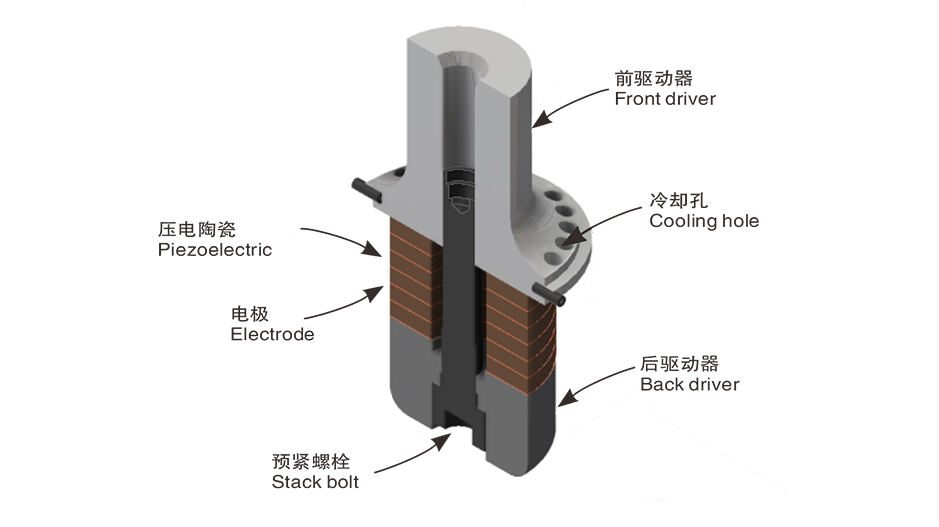
Os transdutores ultrasónicos funcionam transformando energia elétrica em ondas sonoras de alta frequência de que falamos tanto hoje em dia, geralmente entre 20 kHz e 200 kHz, e podem fazê-lo de ambos os lados também. O que torna tudo isto possível são materiais especiais que mudam de forma quando são atingidos por eletricidade ou magnetismo, criando as pequenas vibrações mecânicas que precisamos. Tomemos cristais piezoelétricos como um bom exemplo. Aplique alguma tensão e observe-as crescer ou encolher, enviando ondas de pressão que se movem através do ar, da água, até mesmo de objetos sólidos. E aqui está a parte inteligente: quando estes mesmos cristais captam ecos de outro lugar, basicamente viram as coisas outra vez, transformando esses movimentos mecânicos em sinais elétricos que podemos medir. A maioria das indústrias depende muito deste efeito piezoelétrico porque funciona tão bem e permanece confiável ao longo do tempo. Pensem nos equipamentos médicos de imagem ou nos testes que verificam a integridade estrutural sem danificar nada. Praticamente tudo nesse espaço depende deste princípio básico a funcionar perfeitamente dia após dia.
Mecanismos piezoelétricos, magnetostritivos e capacitivos comparados
| Mecanismo | Princípio de Funcionamento | Melhor para | Pontos Fortes | Limitações |
|---|---|---|---|---|
| Piezoelétrico | Deformação do campo elétrico | Imagem médica, limpeza | Alta sensibilidade, ampla frequência | Fraco, sensível à temperatura |
| Magnetostrictive | Deformação induzida por campo magnético | Soldadura industrial | Alta potência, durabilidade | Frequência limitada, custo mais elevado |
| Capacitivo | Força electrostática | Sensores de precisão | Compacto e com baixo consumo de energia | Falta de potência, circuitos de acionamento complexos |
Os transdutores piezoelétricos dominam devido à sua versatilidade, enquanto as variantes magnetostrictive se destacam em aplicações de alta potência como corte de metal. Os projetos capacitivos, embora menos comuns, oferecem uma precisão superior para medições de micro-distâncias em ambientes controlados.
Tendências emergentes: Transdutores ultrasônicos compostos e baseados em MEMS
Os últimos desenvolvimentos na tecnologia de transdutor são todos sobre compósitos que misturam cerâmica piezoelétrica com vários polímeros. Esta combinação ajuda a aumentar a faixa de frequências que esses dispositivos podem lidar e os faz funcionar melhor quando colocados contra diferentes materiais. Ao mesmo tempo, estamos a ver a tecnologia MEMS a fazer grandes progressos. Estes pequenos sistemas micro-eletromecânicos estão a alimentar tudo, desde pequenos equipamentos de diagnóstico até sensores da Internet das Coisas. Alguns desses componentes MEMS medem menos de um milímetro de diâmetro, mas ainda conseguem operar em frequências de cerca de 1 milhão de ciclos por segundo. Tomemos por exemplo as ecografias endoscópicas. As versões mais recentes que usam a tecnologia MEMS são cerca de metade do tamanho dos modelos mais antigos, o que significa que os pacientes experimentam menos desconforto durante os procedimentos, enquanto ainda obtêm imagens claras. À medida que as instalações médicas continuam a pressionar por soluções de monitorização menores e mais versáteis, especialmente em áreas do corpo de difícil acesso, este tipo de melhorias tecnológicas estão a tornar-se cada vez mais valiosas.
Tipos principais de transdutores ultrasônicos: características e casos de uso
Transdutores piezoelétricos: mais amplamente utilizados para aplicações amplas
De acordo com o Material Science Quarterly de 2023, cerca de três quartos de todas as aplicações industriais e médicas dependem de transdutores ultra-sônicos piezoelétricos porque esses dispositivos convertem energia para trás e para frente de forma tão eficiente. Estes transdutores normalmente contêm materiais como titanato de zirconato de chumbo, comumente conhecido como PZT, que cria essas ondas sonoras de alta frequência quando a eletricidade flui através dele. O projeto é bastante simples, mas durável o suficiente para ambientes exigentes, fazendo com que funcionem bem para coisas como máquinas de ultra-som em hospitais, encontrar fugas em tubulações, e até ajudar os condutores a estacionar carros com segurança. Eles operam em um amplo espectro de frequências que vão de 20 kilohertz a 10 megahertz, permitindo que os engenheiros ajustem a profundidade de penetração dos sinais versus o quão detalhadas as imagens resultantes precisam ser, dependendo do que exatamente precisa de inspeção.
Transdutores magnetostrictivos: ideais para utilização industrial de alta potência
Os transdutores magnetostrictivos funcionam bem para trabalhos difíceis como verificar oleodutos ou operar sistemas de sonar subaquático. Estes dispositivos normalmente usam ligas de níquel para transformar campos magnéticos em poderosas vibrações mecânicas. Eles têm de três a cinco vezes mais energia do que as alternativas piezoelétricas normais. O lado negativo? A sua faixa de frequência é muito estreita, entre 20 e 100 kHz, o que limita a detalhadão das leituras. Mas o que as diferencia é a sua durabilidade em condições de calor extremo. A maioria dos modelos continua a funcionar corretamente mesmo quando as temperaturas atingem cerca de 300 graus Celsius. Esse tipo de resiliência torna estes transdutores indispensáveis em indústrias onde ambientes de alta temperatura são comuns, como laboratórios de testes de metais e refinarias de petróleo que precisam de monitorização constante.
Transdutores capacitivos e compostos: sensibilidade versus durabilidade
Os transdutores capacitivos dão sinais muito claros quando usados para sistemas de detecção de gás e para conjuntos de microfones porque funcionam modulando campos eletrostáticos. O problema é que essas membranas finas precisam de algum tipo de proteção contra todo o tipo de desgaste ambiental. Se olharmos para os transdutores compósitos, estes têm fibras piezoelétricas misturadas com materiais polímeros, o que os ajuda a combinar melhor os sons e a durar mais tempo. Algumas versões mais recentes feitas com reforço de fibra de carbono mostram uma resistência a impactos cerca de 40 por cento melhor sem perder esse nível de detalhe submicrômetro. Isso os torna perfeitos para testar peças em aplicações aeroespaciais, onde os engenheiros precisam de extrema precisão e componentes que possam lidar com manuseio áspero durante os testes.
Projetos avançados de transdutor: matriz de fases, feixe angular e ferramentas especializadas
Testes ultrasônicos em matriz de fases (PAUT): controlo dinâmico do feixe
O teste de ultrassom de matriz em fases, ou PAUT, abreviadamente, funciona usando vários elementos de transdutor juntos para controlar e direcionar feixes de ultrassom eletronicamente. Isto permite aos inspectores verificar formas e estruturas complicadas que seriam difíceis de verificar com métodos tradicionais. O sistema ajusta pequenas diferenças de tempo entre cada elemento da matriz para que possa direcionar a energia exatamente onde é necessária, tudo sem qualquer movimento mecânico. Isso torna a PAUT particularmente boa para analisar soldagens e materiais compósitos. Uma pesquisa publicada no ano passado na revista Nature Communications descobriu que, quando aplicada a peças usadas em aviões, a PAUT detecta 30% mais defeitos do que as técnicas mais antigas poderiam, graças à sua capacidade de formar feixes sobre a marcha. Para coisas como asas de aviões ou lâminas de turbinas com as suas curvas e camadas, este tipo de precisão realmente importa porque pequenas falhas podem tornar-se grandes problemas no futuro.
Transdutores de feixe de ângulo: inspecção eficaz em geometrias complexas
Os transdutores de feixe de ângulo enviam ondas sonoras em ângulos que variam de cerca de 45 graus a cerca de 70 graus, o que ajuda a detectar as falhas paralelas de superfície complicadas que se escondem sob camadas de isolamento ou ao longo das juntas de tubulações. O cristal especial em ângulo dentro desses dispositivos facilita o bom contato quando se verificam as soldaduras e juntas durante as inspeções. Com as configurações de frequência modernas, tipicamente entre 2 e 10 MHz, os transdutores de feixe de ângulo de hoje conseguem fazer algo impressionante: podem olhar profundamente nos materiais, às vezes até 300 milímetros através do aço, enquanto ainda captam detalhes finos com uma precisão de cerca de meio milímetro Esta combinação de profundidade e precisão é a razão pela qual tantos engenheiros confiam neles para acompanhar a integridade estrutural ao longo do tempo.
Estudo de caso integrado: Inspecção de tubulações com PAUT e feixe angular
Uma análise de aplicações industriais a partir de 2025 mostrou que, quando o PAUT é combinado com transdutores de feixe de ângulo, os tempos de inspeção diminuem cerca de 40% para esses oleodutos e gasodutos. As matrizes de fases funcionam muito bem para mapear a solidez das soldas longitudinais, enquanto as vigas angulares apanham as rachaduras circunferenciais difíceis bem nas articulações do cotovelo, atingindo cerca de 98% de precisão na identificação de falhas. Usar ambos os métodos juntos resolve problemas com que as inspecções técnicas enfrentam dificuldades, o que é muito importante hoje em dia, já que grande parte da nossa infraestrutura está ficando muito velha e precisa de verificações regulares.
estudo de 2023 Nature Communications
Transdutor de contacto versus de imersão: escolha por método de acoplamento
Transdutor de contato: robusto e portátil para uso em campo
Os transdutores de contacto funcionam na superfície dos materiais, normalmente precisam de algo como gel ou óleo para preencher os vazios de ar. Estes dispositivos são construídos duros e pequenos o suficiente para lidar com condições difíceis, que é por isso que as pessoas os usam em todos os lugares, como sistemas de tubulação e zonas de construção ativas. Não há necessidade de tanques de água volumosos, tornando-os bastante portáteis para o que fazem. O lado negativo? Se o acoplamento não for aplicado corretamente, os sinais não passam de forma confiável. Este problema piora quando se lida com superfícies que não são lisas ou têm formas estranhas, algo que os técnicos encontram com bastante frequência em situações do mundo real.
Transdutores de imersão: alta precisão em configurações ligadas a líquidos
Quando se usam transdutores de imersão, tanto o objeto a ser testado quanto o transdutor real são submersos em fluido, geralmente água, de modo que as ondas sonoras viajem de forma consistente. A forma como funciona reduz as inconsistências e dá uma melhor qualidade de imagem, o que torna estes dispositivos excelentes para detectar pequenas falhas em coisas como peças metálicas finas usadas em aviões ou eletrônicos delicados. Claro, a instalação leva algum espaço com todos os tanques de água e partes móveis para a varredura, mas o que estes sistemas não têm em mobilidade eles compensam com uma precisão incrível. Laboratórios e fábricas onde o espaço não é um problema, muitas vezes dependem deles porque nada supera o seu desempenho quando se trata de encontrar problemas difíceis de detectar.
Estratégia de seleção: correspondência de meio, frequência e material
A escolha entre os transdutores de contacto e de imersão depende de três factores principais:
- Médio : As superfícies com apoio de ar funcionam melhor com métodos de contacto que utilizam acopladores viscosos, enquanto as geometrias submersas ou complexas beneficiam da imersão.
- Freqüência : As frequências mais baixas (0,15 MHz) são tipicamente associadas a transdutores de contacto para penetração profunda em aço grosso, enquanto as frequências mais elevadas (1020 MHz) são utilizadas com configurações de imersão para resolução fina em materiais finos ( Física da Análise Ultrasônica 2022 ).
-
Material : Os materiais porosos ou irregulares requerem imersão para acoplamento consistente, enquanto os compósitos lisos podem ser inspecionados eficazmente com transdutores de contato.
A eficiência de campo favorece frequentemente os modelos de contacto, enquanto os requisitos de alta precisão justificam o investimento em sistemas de imersão.
Critérios-chave de selecção: Frequência, sensibilidade e adequação da aplicação
Frequência versus Resolução e Profundidade de Penetração: O que priorizar
A frequência de um transdutor tem um grande impacto tanto na clareza da imagem como na profundidade que ela pode penetrar nos materiais. Quando falamos de frequências mais altas entre 5 e 20 MHz, elas nos dão muito mais detalhes para detectar pequenos problemas. Mas há uma compensação aqui também porque estes sinais são absorvidos mais rapidamente, por isso não funcionam bem em materiais grossos ou misturados. Por outro lado, as frequências mais baixas, que vão de cerca de 500 kHz até 2 MHz, podem chegar mais longe nos materiais, mas não podem mostrar esses detalhes finos. Vejamos este estudo de caso prático: se alguém reduz a frequência pela metade, a penetração aumenta cerca de duas vezes, mas a capacidade de ver pequenas características diminui pela metade de acordo com descobertas recentes de pesquisa. A maioria das lojas que fazem verificações de solda de metais adere a frequências entre 2 e 5 MHz, uma vez que isso lhes dá um bom meio termo. Os fabricantes de semicondutores precisam de algo diferente, porém, indo para frequências acima de 10 MHz para detectar esses defeitos microscópicos durante as verificações de qualidade.
Sensibilidade e largura de banda: alinhamento com as necessidades de detecção
A sensibilidade de um sistema diz-nos qual é a menor falha que podemos detectar, enquanto a largura de banda basicamente mostra quantas frequências diferentes o nosso transdutor funciona com quando envia e recebe sinais. Quando falamos de largura de banda mais ampla, em torno de 70 a 100%, isso nos dá uma informação muito melhor sobre como os materiais reagem de forma diferente e ajuda a identificar todos os tipos de defeitos também. É por isso que estes sistemas de banda larga funcionam tão bem para mapear problemas de corrosão em superfícies. Por outro lado, os transdutores de banda estreita podem não lidar com tantas situações, mas são excelentes em apanhar aquelas pequenas rachaduras que se formam em partes importantes das estruturas das aeronaves. Olhando para o que os especialistas da indústria recomendam para sensores hoje em dia, combinar a largura de banda certa com o tipo de falhas que esperamos, faz o diagnóstico muito mais preciso. E adivinha? Aquelas trocas complicadas entre largura de banda e sensibilidade não são impossíveis de lidar com qualquer um. Basta colocar um bom pré-amplificador em algum lugar ao longo da linha e de repente as coisas começam a funcionar melhor juntas.
Superando desafios: uso de alta frequência em ambientes de sinal fraco
Os transdutores de alta frequência acima de 10 MHz enfrentam sérios problemas de perda de sinal quando utilizados em materiais que absorvem ondas sonoras, como fundidos metálicos ou tecidos vivos. Os engenheiros desenvolveram configurações de dois elementos, juntamente com lentes de forma especial, para focar melhor a energia acústica, o que ajuda a aumentar essas importantes proporções sinal/ruído. Alguns métodos de processamento de sinal bastante inteligentes estão agora disponíveis também. A média de sinal, por exemplo, pode reduzir o ruído de fundo em cerca de 12 a talvez 15 decibéis, mesmo em situações em que o sinal é fraco, tudo isso mantendo uma boa operação em tempo real de acordo com pesquisas recentes do IEEE Sensors em 2023. Quando se medem materiais muito finos com menos de 1 milímetro de espessura, os fabricantes frequentemente recorrem a transdutores compósitos com camadas de amortecimento adicionais. Estes projetos especiais oferecem excelente precisão de alta frequência, além de sinais muito mais limpos em geral.
Perguntas frequentes
Para que são usados os transdutores de ultra-som?
Os transdutores ultrasônicos são usados em uma ampla gama de aplicações, incluindo imagem médica, soldagem industrial, inspeção de tubulações e teste de metais. Eles convertem energia elétrica em ondas sonoras de alta frequência para inspecionar ou analisar materiais.
Como funcionam os transdutores de ultra-som piezoelétricos?
Os transdutores piezoelétricos usam o efeito piezoelétrico para converter energia elétrica em vibrações mecânicas. Os materiais, como cristais piezoelétricos, mudam de forma quando a tensão é aplicada, enviando ondas de pressão para o meio que estão inspecionando.
Qual é a diferença entre transdutores piezoelétricos e magnetostritivos?
Os transdutores piezoelétricos operam através da deformação do campo elétrico, oferecendo alta sensibilidade e amplas faixas de frequência, mas são frágeis e sensíveis à temperatura. Os transdutores magnetostritivos empregam tensão induzida por campo magnético para fornecer alta potência e durabilidade, embora tenham frequência limitada e custo maior.
O que são transdutores de ultra-som baseados em MEMS?
Os transdutores baseados em MEMS incorporam sistemas micro-eletromecânicos, permitindo componentes pequenos e eficientes que operam em altas frequências. São utilizados em várias aplicações, incluindo pequenos equipamentos de diagnóstico e sensores IoT.
Sumário
- Como Transdutores ultrassônicos Trabalho: Princípios e tecnologias fundamentais
- Tipos principais de transdutores ultrasônicos: características e casos de uso
- Projetos avançados de transdutor: matriz de fases, feixe angular e ferramentas especializadas
- Transdutor de contacto versus de imersão: escolha por método de acoplamento
- Critérios-chave de selecção: Frequência, sensibilidade e adequação da aplicação
- Perguntas frequentes